
In practice: An EV traction motor rotor is balanced in two planes on an automatic machine, usually by removing a small amount of material from balance rings or end plates at each end of the rotor. The tolerance is much tighter than for an industrial motor, because the rotor runs several times faster and there is no engine noise to hide what is left.
Why EV rotors are a harder job
Speed. An industrial motor on mains supply runs at a few thousand rpm. Traction motors commonly run to 15,000 to 20,000 rpm, and the trend is upward. The force from a given unbalance rises with the square of speed, so the same heavy spot does many times the work at the top of the range.
Noise. In a combustion vehicle the engine masks most driveline noise. In an electric one, a once-per-revolution vibration from the motor is heard in the cabin as a whine or a boom.
Bearings and clearances. Rotor bearings are small and fast, and the air gap between rotor and stator is narrow. Unbalance load shortens bearing life.
Small numbers. The permitted unbalance on a fast rotor is a few gram-millimeters per plane. At that level the machine, the tooling and the cleanliness of the part all matter.
Rotor types and where correction can go
| Rotor type | Construction | Where balance correction is usually made |
|---|---|---|
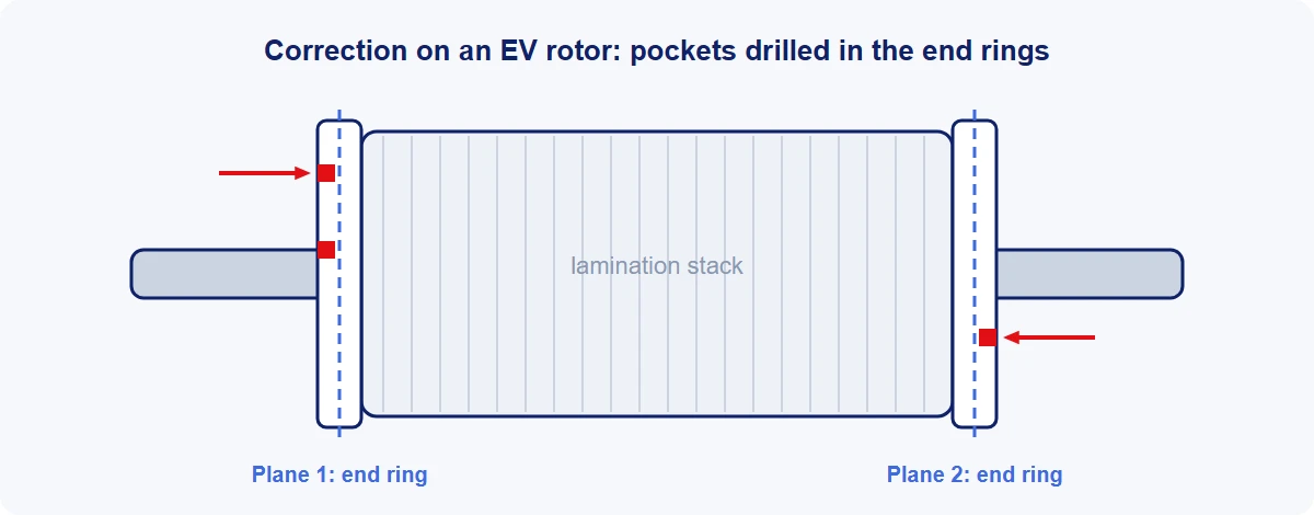
| Interior permanent magnet | Laminated steel stack with magnets set in pockets, held between end plates | End plates or balance rings at each end |
| Induction | Laminated stack with a cast or fabricated aluminum or copper cage | The end rings, or added balance rings |
| Wound (externally excited) | Laminated stack carrying copper windings and slip rings | Added material, or balance rings |
| Axial flux | A flat disc carrying magnets | The disc face or rim |
The lamination stack itself is not normally cut. Drilling into it would disturb the magnetic circuit, and the swarf is steel.
Where the unbalance comes from
- The lamination stack. Stamped laminations vary slightly in thickness across the sheet, and a stack of several hundred builds that into a wedge unless the laminations are rotated as they are stacked, which most manufacturers do.
- Magnets. Each magnet differs a little in mass, and each sits somewhere within the clearance of its pocket. Adhesive or resin fill adds its own variation.
- The shaft. Runout between the bearing journals and the seat for the stack moves the whole stack off-center.
- End plates, rings and cages. Castings and pressed parts with their own tolerances.
- Assembly. A press or shrink fit never seats perfectly evenly.
Measuring
The rotor is supported on its own bearing journals and spun, usually by a belt on the stack or the shaft, so that no drive coupling adds an error of its own. Sensors at each support measure the force, and the machine converts it into an amount and an angle in each of the two correction planes.
Three things decide whether the reading can be trusted at these tolerances:
- The journals. The rotor is measured on the surfaces its bearings will sit on. Any dirt or damage there is measured as unbalance.
- Plane separation. The machine has to tell the left-hand plane from the right. On a short, stiff rotor with planes close together this is harder, and it is worth testing.
- The machine's own limit. The smallest unbalance a machine can resolve should be several times smaller than the tolerance. See balancing machine calibration.
Axial flux rotors are discs, not shafts, and are generally measured on a vertical machine.
Correction methods
Removing material is the usual production method.
- Drilling into a balance ring or end plate is fast and easy to automate. The machine works out the depth and angle, and often splits one correction into two or more holes to stay within a depth limit.
- Milling removes a shallow arc instead of holes. It spreads the cut and suits thin rings.
Adding material is used where there is nothing that can safely be cut, and in low-volume and repair work: balancing putty or epoxy, washers or clips. Some production rotors are corrected by adding small weights automatically, welded on by laser, so nothing is cut at all.
Three practical points:
- Swarf. Once the magnets are in, the rotor attracts steel. Balance rings are made of non-magnetic material such as aluminum or stainless steel partly for this reason, and the cutting station needs extraction that captures the chips at the tool.
- Correction capacity. A balance ring only has so much metal. If the incoming unbalance is too high, the rotor cannot be brought in. The cure is upstream, in stacking and magnet insertion.
- Audit run. After correction the rotor is measured again. A good process brings most rotors into tolerance with one correction; if it routinely takes two, look at the machine's URR and the incoming unbalance.
What tolerance to specify
ISO balance quality grade G 2.5 is the grade most often quoted for electric motor rotors, and many traction motor programmes ask for tighter, usually as a figure in g·mm per plane. The tolerance is worked out for the maximum service speed, even though the rotor is measured at a much lower speed on the machine.
Worked example. A rotor of 12 kg with a maximum speed of 16,000 rpm, to G 2.5:
Uper = 9,549 × G × m ÷ n = 9,549 × 2.5 × 12 ÷ 16,000 ≈ 18 g·mm in total, or about 9 g·mm in each plane
That is the same as the rotor's center of mass sitting about 1.5 micrometers off its axis, a fraction of the thickness of a human hair. The same rotor at an industrial 3,000 rpm would be allowed more than five times as much.
The formula and grades are explained in ISO 21940 balance grades explained.
Does the balance hold at speed?
Low-speed balancing assumes the rotor is rigid: that it keeps the same shape at 16,000 rpm as at 1,000. Traction rotors are designed to run below their first bending speed, so the shaft itself generally behaves.
What can change is the mass inside. Under high centrifugal load and at operating temperature, magnets can settle outward in their pockets and a stack can shift slightly on the shaft. If that happens unevenly, the balance moves. Manufacturers deal with it in the design, with tight pockets and resin fill, and some add a spin to speed before balancing so that anything that is going to settle does so first.
Unbalance is only one source of motor noise
Unbalance produces vibration at once per revolution. An electric motor also produces vibration and noise at higher multiples of speed, from the magnetic forces between rotor poles and stator slots and from the inverter's switching. Balancing does nothing for those. If a motor is noisy at a high order, the cause is electromagnetic or structural, not balance.
In the production line
On a volume line the balancing station is automatic: the rotor is identified, loaded by robot or gantry, measured, corrected, measured again and unloaded, with the initial and final unbalance stored against its serial number. Cycle time is set mainly by spin-up and spin-down and by the number of cuts.
Because the tolerances are so small, the station itself is checked regularly with a reference rotor, and its repeatability is studied in the same way as any other gauge on the line.
After balancing, the assembled motor goes on to end-of-line testing for noise, vibration and performance.
Machines for the job
Standard rotors are usually balanced on horizontal belt-drive machines, while disc-type axial flux rotors may be better suited to vertical machines. Automation ranges from manual systems to fully automated, robot-fed machines for high-volume motor production.