
Short answer: A driveshaft is balanced dynamically, as a complete assembly, spinning at or near the speed it runs at in the vehicle. The machine measures the unbalance near each end of each tube and correction weights are attached there. A one-piece shaft is corrected in two planes; each extra section adds a plane, so a two-piece shaft uses three and a three-piece shaft four.
Driveshaft, propshaft, prop shaft and cardan shaft all mean the same part here.
Why a driveshaft is out of balance to begin with
A driveshaft is a thin tube with a heavy fitting welded on each end, and each of those brings its own error:
- Tube wall thickness. Welded and drawn tube is never perfectly even around its circumference. A wall that is slightly thicker on one side puts mass off-center along the whole length.
- Tube straightness. A small bow moves the middle of the tube off the axis of rotation.
- Weld-yoke and flange runout. If a yoke is welded on slightly off-center or at a slight angle, the tube runs out even though the tube itself is straight.
- Joints and splines. Universal joints, constant-velocity joints and slip splines all have clearance. The shaft settles to one side of that clearance when it spins.
This is why the parts cannot simply be balanced one at a time. Every component can be within its own limits and the assembly still be out, because the errors add up differently each time. The finished shaft is balanced as it will run.
What unbalance does in the vehicle
An unbalanced shaft produces a force that goes round once per revolution. The driver feels it through the floor or seat, or hears it as a boom, at a particular road speed. The force rises with the square of speed, so a shaft that is fine at 50 mph (80 km/h) can be unpleasant at 80 mph (130 km/h).
Over time the same force loads the center bearing, the joints, the transmission tail bearing and the axle pinion bearing.
Not every driveline vibration is unbalance. Universal joints working at an angle produce a vibration at twice shaft speed, and that is a geometry problem that no amount of balancing will remove. A vibration at once per revolution points to unbalance or runout; one at twice per revolution points to joint angles or phasing.
How many planes?
A correction plane is a position along the shaft where weight can be added. A rigid rotor needs two planes to correct both the static unbalance and the couple (see static vs dynamic balancing).
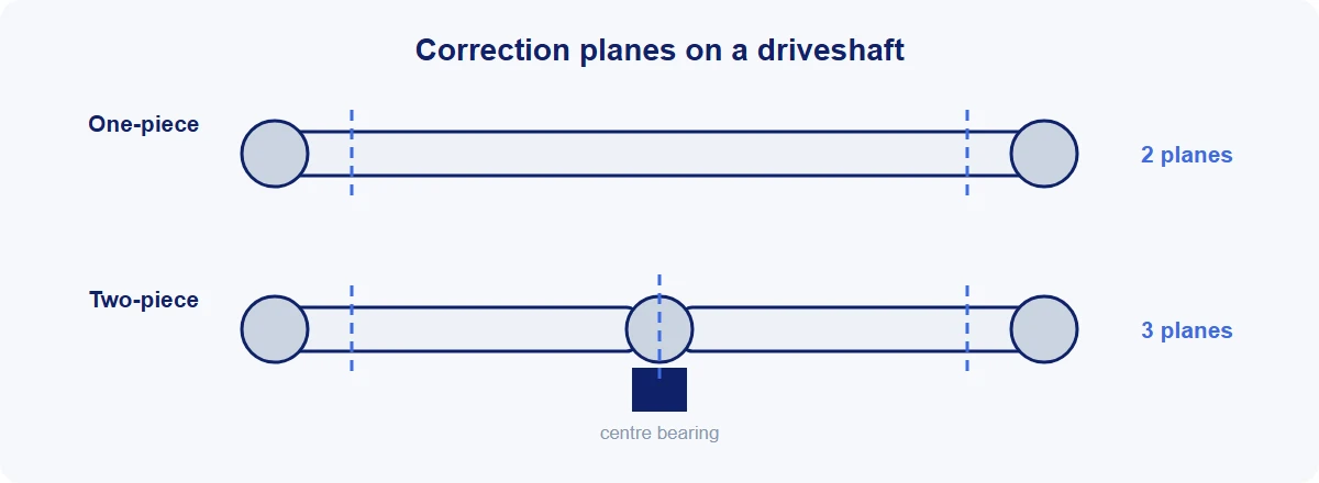
- One-piece shaft: two planes, one near each end of the tube.
- Two-piece shaft: three planes. The two tubes meet at a center bearing, and a plane is needed there as well as at the outer ends.
- Three-piece shaft: four planes, for the same reason.
Each tube in a multi-piece shaft is supported and can move at its joints, so the unbalance of one section is not cancelled by a weight on another. Each section has to be corrected where it is.
Why the shaft is balanced at or near service speed
Most rotors are balanced at a low speed and stay balanced at any speed, because they are stiff. A driveshaft is long and thin. As speed rises it begins to bow outward slightly at the middle, and the faster it goes the more it bows, up to its critical speed, where it would whip.
Shafts are designed so the critical speed is safely above anything the vehicle can reach. Splitting a long shaft into two or three shorter ones is one of the main ways of doing that. Even so, a shaft running at highway speed is flexing a little, and its balance at that speed is not quite the same as its balance when turning slowly.
So driveshafts are balanced at a speed representative of how they are used, not at the low speeds used for stiff rotors. Our manual propshaft machines run from about 1,500 to 4,000 rpm. Driveshaft machines are also usually soft-bearing, unlike most of our machines, because the long flexible shaft is best measured on supports that move with it.
How the shaft is held
The shaft has to be mounted the way it sits in the vehicle, because every clearance described above will settle differently if it is not.
- It is driven from one end through its own flange or yoke.
- A two- or three-piece shaft is supported at its center bearings, in their own rubber mounts.
- Slip splines are set to their working length.
- The machine's own adapters have to run true. An adapter that is itself off-center adds an error to every shaft. The check is simple: measure a shaft, turn it 180° on the adapter and measure again. Unbalance that turns with the shaft is real; anything that stays with the adapter is tooling error, and it is worth finding before you weld a weight to compensate for it.
Straightness comes first
Runout is measured before balancing. A tube that runs out too far is rejected or straightened, not balanced, for two reasons. Balancing a bent tube takes a large weight, and the correction is only right at one speed, because the bend and the weight respond differently as the shaft flexes. See how automatic shaft straightening works.
How correction is done
On steel tubes the standard method is to weld small steel weights to the outside of the tube, close to the end fittings. In production the machine measures, selects a weight of the right mass, places it at the right angle and welds it automatically, then spins the shaft again to confirm the result.
Aluminum and carbon fiber shafts can't take a steel weight welded to the tube. Aluminum shafts use aluminum weights, or weights at the end fittings; composite shafts are corrected at the metal end fittings or with bonded weights.
Two limits apply whatever the material. A weld must not damage the tube or its coating, and there is a maximum weight per plane. A shaft that needs more than that is telling you something is wrong with the tube or the yoke weld. Reject it; don't hide it under a big weight.
What tolerance to specify
Vehicle manufacturers normally give the limit directly, as a residual unbalance per plane at a stated speed, in g·cm, g·mm or oz·in. That figure, the speed and the mounting method together are the specification. A limit without a speed and a mounting method cannot be checked.
Where no figure is given, the ISO balance quality grades are the usual starting point. The grade table has long listed drive shafts under G 40, and drive shafts with special requirements under G 16.
Worked example. A shaft of 10 kg running at 3,000 rpm, to G 16:
Uper = 9,549 × G × m ÷ n = 9,549 × 16 × 10 ÷ 3,000 ≈ 509 g·mm in total, or about 255 g·mm in each of two planes
The formula and the grades are explained in ISO 21940 balance grades explained. In practice most vehicle makers give their own figure per plane, and it is usually tighter than this.
Production lines and repair shops
The physics is the same; the equipment is not.
- Vehicle production uses automatic machines: the shaft is identified, loaded, measured, corrected by automatic welding, re-measured and unloaded, and the result is recorded against the part. Runout is often measured in the same station, and the high point marked so the shaft can be matched to the axle flange at assembly.
- Aftermarket and repair shops see every length and type of shaft, one at a time. They need an adjustable bed length, quick changes of adapter and manual or semi-automatic correction.
Balance & Test driveshaft balancing machines come in 2, 3 or 4 plane configurations for production, and up to 5 planes on manual machines, with automatic versions for light and heavy-duty vehicle lines and manual and semi-automatic versions for the aftermarket.