
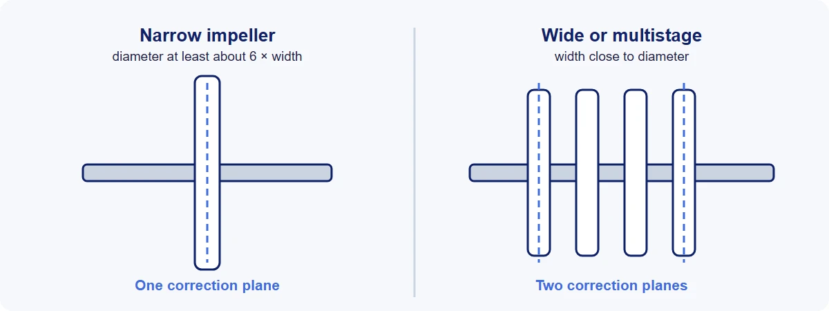
Rule of thumb: A narrow impeller is balanced in one plane and a wide one, or a multistage rotor, in two. Most pump impellers are specified to ISO balance quality grade G 6.3, with G 2.5 for higher speeds and more demanding duties. Correction is made by removing metal from the shrouds, never from the vanes.
Why an impeller needs balancing
An impeller is a casting, and castings are not symmetrical:
- Core shift. If the core that forms the water passages sits slightly off-center in the mold, the shrouds and vanes come out thicker on one side.
- Uneven vane and shroud thickness, and local porosity.
- Machining offsets. If the bore is not concentric with the outside, the whole mass runs off-center.
- Later work. Trimming the diameter, fitting wear rings and applying coatings all change the balance. An impeller should be balanced after these, not before.
The effects of running one out of balance are the familiar ones: vibration at running speed, shaft deflection, and early wear of mechanical seals, wear rings and bearings.
One plane or two?
Unbalance comes in two forms. Static unbalance is the center of mass sitting off the axis. Couple unbalance is two equal heavy spots at opposite ends and opposite sides, which rock the rotor. One correction plane can fix the first; fixing both takes two planes. See static vs dynamic balancing.
Whether couple unbalance matters depends on shape:
- A narrow impeller is close to a disc. There is little axial length for a couple to develop, so single-plane balancing is normally enough.
- A wide impeller, such as a double-suction or mixed-flow design, can carry a significant couple and needs two planes.
- A multistage rotor is always a two-plane job once assembled.
The usual test is the ratio of diameter to width. Pump industry guidance has long allowed single-plane balancing where the diameter is at least six times the width, and many pump makers apply the same rule across their ranges.
Which grade?
The balance quality grade sets how much residual unbalance is allowed for a rotor of a given mass and service speed.
- G 6.3 is the grade the ISO table has long given for pump impellers, and it is the common default for general-purpose pumps.
- G 2.5 is used for higher-speed pumps, turbine-driven pumps and anywhere vibration limits are tight. API 610 calls for G 2.5 on impellers and other major rotating parts.
Always use the service speed in the calculation, even though the balancing machine runs slower. An impeller is a rigid rotor, so it can be measured at a convenient low speed; what changes with service speed is how much unbalance is permitted.
Worked example. An impeller of 20 kg running at 3,600 rpm (a two-pole motor on 60 Hz). On 50 Hz it would run at about 2,950 rpm and be allowed about 20% more.
To G 6.3: Uper = 9,549 × 6.3 × 20 ÷ 3,600 ≈ 334 g·mm
To G 2.5: Uper = 9,549 × 2.5 × 20 ÷ 3,600 ≈ 133 g·mm
For single-plane balancing the whole amount applies in the one plane. For two planes on a symmetrical impeller it is split, half to each. For an overhung impeller the tolerance is set at the bearings and shared out by distance; ISO 21940-11 shows how.
The formula and the grade table are in ISO 21940 balance grades explained.
Mounting: where most of the error comes from
An impeller has no journals of its own. It is balanced on a mandrel (also called an arbor) in a horizontal machine, or on an adapter or chuck in a vertical one. Whatever error the mounting has, the machine reads as impeller unbalance.
- Fit. If the bore is loose on the mandrel, the impeller sits off-center by the clearance, and by a different amount each time it is fitted. An expanding mandrel or a close fit removes this.
- Mandrel runout and unbalance. The mandrel is balanced on its own first, and has to run true.
- Keys. An impeller with a keyway is missing metal on one side; the shaft has a keyway too, and the key fills both. The convention in ISO 21940-32 (which replaced ISO 8821) is to balance each part with a half key. Parts balanced to different key conventions won't be balanced when assembled, so the drawing should say which was used.
Index balancing separates the two sources of error. Measure the impeller, turn it 180° on the mandrel and measure again. Unbalance that turns with the impeller belongs to the impeller. Unbalance that stays put belongs to the mandrel or the mounting, and can be subtracted.
Correction by impeller type
Metal is removed from the heavy side, on a face where it does no harm.
- Closed and semi-closed impellers are corrected on the outer faces of the shrouds, by grinding in low volumes and repair work, or by milling in automatic machines. The cut should be shallow and spread over an arc, blended smoothly into the surface, and kept as far out in radius as practical so that the least metal does the most good.
- Open impellers have no front shroud. They are corrected by grinding the back of the hub plate or the back edges of the vanes, or by welding weights to the blades.
Three rules apply to all of them:
- Stay out of the water passages. Grinding the working face of a vane changes the hydraulics and can create a different vibration problem.
- Respect the shroud thickness. Pump makers set a limit on how deep a correction may go. An impeller that can't be brought in within that limit is a casting reject, not a balancing job. This is one of the quiet benefits of automatic correction: nobody removes more metal than the casting can safely lose.
- No sharp steps or notches. They are stress raisers and, in some services, sites for cavitation or corrosion.
Component balance and assembly balance
For a single-stage pump, balancing the impeller is usually the whole job. For a multistage pump there are two steps:
- Each impeller, and any balance drum or sleeve, is balanced on its own.
- The rotor is then assembled on its shaft and balanced again in two planes.
The second step is needed because small residual errors in each part, and in each fit on the shaft, add up along the rotor. If parts have to be removed again to build the pump, their positions are marked so they go back the same way round.
What balancing does not fix
A balancing machine measures the impeller spinning in air. Two pump vibration sources will not show:
- Hydraulic unbalance. If the vane passages are not identical, the water exerts an uneven force once per revolution when the pump is running. It looks like mechanical unbalance on a vibration analyzer and comes from the casting, not the mass distribution.
- Vane-pass vibration, at running speed times the number of vanes, which comes from the clearance between the impeller and the casing cutwater.
If a pump vibrates at running speed with a correctly balanced impeller, check runout, fits and hydraulic unbalance before balancing it again.
Common mistakes
- Balancing before the final trim, wear rings or coating.
- Using the balancing-machine speed, not the service speed, to work out the tolerance.
- Ignoring the key convention, or mixing half-key and full-key parts.
- A loose fit on the mandrel, and no index check.
- Correcting on the vanes, or cutting one deep notch where a long shallow one was needed.
- Single-plane balancing a wide impeller.
What the balance record should show
Part and serial number; the grade, service speed and resulting tolerance; the number of planes; the key convention; initial and final unbalance in each plane; and the machine, operator and date. More pump buyers now ask the question nobody used to ask: can you show me? With the record kept, a warranty claim three years later is a data lookup rather than an argument.
Machines for the job
Horizontal balancing machines are typically used for multistage and two-plane impellers, and vertical machines for impellers that need one plane. Automatic correction is worth a look even at modest volumes: one pump maker we worked with automated at a few thousand impellers a year, not for the volume, but so every part met the same tolerance whoever was on shift.