
Key facts: A balance quality grade, written G followed by a number, sets how much residual unbalance a rotor is allowed. The number is a velocity in mm/s. From the grade, the rotor's mass and its service speed you can calculate the permissible unbalance in g·mm.
Uₚₑᵣ = 9,549 × G × m ÷ n
where m is rotor mass in kg, n is service speed in rpm and Uₚₑᵣ is in g·mm.
Where the grades come from
Balance quality grades are defined in ISO 21940-11, the part of the ISO 21940 series that covers balance tolerances for rigid rotors. It replaced ISO 1940-1, which is why older drawings still say "balance to ISO 1940 G 6.3". The grades themselves carried over.
What the number means
The G number is the product of two things:
- eₚₑᵣ, the permissible residual specific unbalance: how far the rotor's center of mass may sit from the axis of rotation, in micrometers (the same as g·mm per kg), and
- ω, the rotor's angular speed in service, in rad/s.
G = eₚₑᵣ × ω, in mm/s
So G 6.3 means the center of mass may move at up to 6.3 mm/s around the axis at service speed. The faster the rotor runs, the smaller the offset allowed. Each grade is 2.5 times the one below it. In practice: a fan at 1,500 rpm to G 6.3 may carry about 40 g·mm per kg of its own weight. On a 40 kg fan that is roughly 1,600 g·mm, and five grams at 550 mm radius is already 2,750 g·mm.
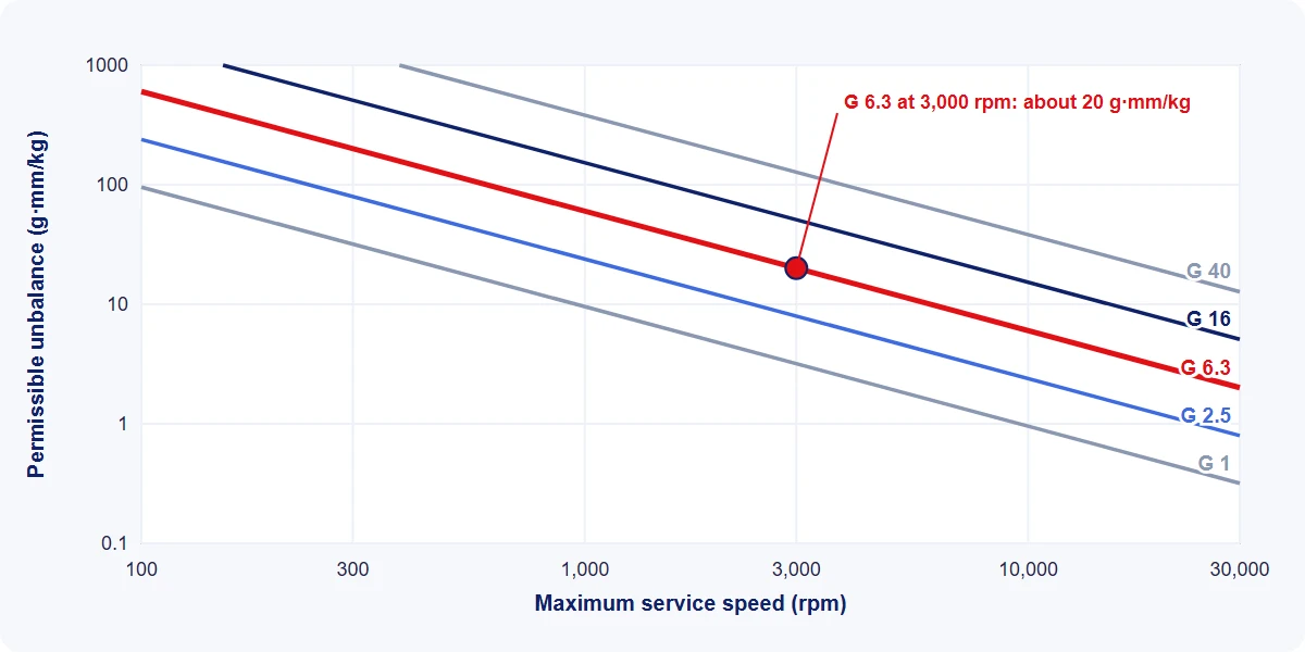
The grade table
| Grade | Typical rotors |
|---|---|
| G 0.4 | Gyroscopes; spindles and drives of high-precision systems |
| G 1 | Grinding machine drives; small high-speed armatures; audio and video drives |
| G 2.5 | Gas and steam turbines; turbo-compressors; machine-tool drives; turbine-driven pumps; medium and large electric armatures with special requirements |
| G 6.3 | Fans; pump impellers; flywheels; general machinery and machine-tool parts; ordinary electric motor armatures; process plant machinery |
| G 16 | Driveshafts (cardan and propeller shafts); parts of agricultural and crushing machinery |
| G 40 | Car wheels, rims and wheel sets; driveshafts; crankshaft drives that are inherently balanced, elastically mounted |
| G 100 | Complete reciprocating engines for cars, trucks and locomotives; crankshaft drives that are inherently balanced, rigidly mounted |
| G 250 | Crankshaft drives that are inherently unbalanced, rigidly mounted |
| G 630 | Crankshaft drives that are inherently unbalanced, elastically mounted |
| G 1600, G 4000 | Large slow marine diesel crankshaft drives |
Examples as published in the ISO 1940-1 table and carried into ISO 21940-11. Check the current edition for your type of machine.
The table is guidance. Where a drawing, customer specification or product standard states a grade, that takes priority.
Worked example
A fan rotor weighs 20 kg, runs at 3,000 rpm and is to be balanced to G 6.3.
- Uₚₑᵣ = 9,549 × 6.3 × 20 ÷ 3,000 = 401 g·mm for the whole rotor.
- With two correction planes placed symmetrically about the center of mass, each plane gets half: about 200 g·mm per plane.
- If correction weights go on at a radius of 100 mm, that is 200 ÷ 100 = 2.0 g per plane.
In imperial units, 401 g·mm is about 0.56 oz·in (1 oz·in is roughly 720 g·mm). Many US drawings give the tolerance directly in oz·in per plane: 0.001 oz·in is only 0.72 g·mm, which is small-turbine-wheel territory and needs a small, sensitive machine.
Splitting the tolerance between planes
Half each only applies when the planes are symmetric about the center of mass. If the center of mass is closer to one plane, that plane takes a larger share, in proportion to the distances. For overhung rotors and rotors with correction planes outside the bearings, ISO 21940-11 gives specific methods, and the tolerance is best set at the bearing planes.
Points that catch people out
- Use the service speed, not the balancing speed. A rigid rotor can be balanced at a few hundred rpm to a tolerance calculated for 10,000 rpm.
- A lower G number is tighter. G 2.5 allows 2.5 times less unbalance than G 6.3.
- Tighter isn't always better. Each step tighter costs time, and below a certain point the result is limited by the tooling, the journals or the fit of the part, not the machine. Specify what the part needs in service, not the tightest number you can find.
- The grade applies to the rotor as it will run. Keys, fitted parts and assembly fits change the result. ISO 21940-32 covers the shaft and fitment key convention.
- The grades are for rigid rotors. Flexible rotors, which change shape as they pass through critical speeds, are covered by ISO 21940-12.
Other parts of ISO 21940 worth knowing
| Part | Covers |
|---|---|
| ISO 21940-11 | Balance tolerances for rigid rotors (the G grades) |
| ISO 21940-12 | Flexible rotors |
| ISO 21940-14 | Assessing balance errors |
| ISO 21940-21 | Describing and evaluating balancing machines |
| ISO 21940-32 | Shaft and fitment key convention |